
Unfortunately they took the minimalism a bit too far. The keyboard has no power switch.
The keyboard goes into deep sleep when no keys are pressed for a while, which is nice enough if it's left sitting on a desktop - but pretty hopeless for a travel keyboard. It lives in my backpack and half the time it comes out flat because a key has been left pressed.
I recently got around to addressing this unfortunate limitation, which brings me to the following less than beautiful but highly effective hardware hack:

I didn't exactly nail the switch placement, but it works wonders. The switch is nearly flush to the case so it doesn't tend to get operated accidentally, and since I added it I've had exactly zero battery-dead incidents.
Adding it was simple enough.
Minimum supplies and tools required
You'll need a small switch that you can fit into the case. Any little switch will do, but I suggest something low that can be kept pretty flush to the casing but not so fiddly you can't easily operate it without tools. (So avoid DIP switches unless you have micro fingers). I used the switch depicted here. Similar switches are very widely available. It's more convenient to use a SPST switch so you only have two terminals to worry about, but this was what I had to hand already.

You also need a small amount of fine insulated electrical wire. Any electronics store has it in abundance. I used very thin (don't remember gauge) solid core copper wire with red insulation, but really pretty much anything that's not too thick will work here.
This is a soldering job, so you need to be able to solder or willing to try it out. If you've never soldered anything before you can still do this as it's a very easy job, but I still suggest trying a few practise wires and pins and so on first. Please use lead-free solder and work in an outdoor or well ventilated environment, rosin fumes aren't something you want to have regular or intense exposure to. If you don't have any gear, all you need is a basic soldering iron (though a temp controlled one is much nicer) and maybe a 10cm length of electrical solder wire.
I made a list of extra tools at the end of the post. They're all really handy to have and make these sorts of tasks much easier. But none of them are necessary for this simple job.
The TL;DR
If you know what you're doing already, you don't need this guide. But all I did was took a small switch and found a spot it'd fit inside the case on the top edge above the keypad area near the LED guide. I extended the existing +ve wire that goes from the battery to the keyboard circuit board to reach the switch location. I made another wire to go from the circuit board +ve terminal to the switch. Then I soldered the wires onto the two switch terminals, cut a small hole in the casing to allow access to the switch, and closed it all up.
The steps
(Ignore the hole I put in the bottom in the following pics. I originally wanted to have the switch sticking downward into the well of one of the feet of the keyboard but I couldn't make it fit there).
Take the rubberized feet off to reveal the screws in the keyboard base
Unscrew all screws from the base and put them in a tray. Don't make the mistake I did, ensure the tray is out of the reach of your curious, persistent 2yo kleptomaniac.
Pop the back off the keyboard
Gently remove the silicone mat that drives the key return.

Unscrew the circuit board from the keyboard.

Gently remove the flexible circuit board that makes contact with the keys.

Plan where you'll put your switch. Try to find a place where you'll be able to cut out an opening in the keyboard case to get easy access to the switch slide/lever, and where the switch casing will fit, but where the switch won't interfere with the keys and you'll be able to route wires to it easily. I put it on the righthand side above the pause/play and mute keys, right on the top edge on the upper face of the keyboard. That wasn't quite optimal as I had to remove the light-guide for the LED, but I can't say I care much about that. Remember, don't do what I did. Instead measure and fit-check properly to make sure the switch will fit where you want it before you start.
If your switch has straight pin terminals like mine it's likely you may need to bend the switch terminals to make it fit; if so, do so before soldering not after like I did. Use needle nose pliers and bend very close to the base of the terminal but not right at the base, so it doesn't snap off. (I actually snapped one of mine because I soldered it then bent it a couple times trying to make the switch fit, but I just soldered onto a different terminal instead.)
De-solder the red (+ve) wire from the circuit board. You don't need a solder sucker or solder wick or anything, just melt the solder and the wire will probably pop free. If not it can be nudged free easily while the solder is molten. Don't keep the soldering iron in place longer than needed to melt the solder, you don't want to overheat the board.
If you aren't comfortable doing this, you can cut the red wire to the board somewhere along its length and solder your extension wires onto both cut ends instead.

Measure and cut enough extra wire to go from the loose end of the +ve red wire you de-soldered to the desired location for the switch. Allow some extra length for a wire path that may not be a straight line, for mistakes that make you trim it back, etc. It's easier to shorten than to extend it later.

Strip about 5mm insulation from each end of the length of wire you made. Slip 1-2 cm of narrow heatstrink tubing over it if you have some and slide it well down the wire away from where you'll be joining it. Take one end and twist the exposed end around the exposed end of the original +ve wire you de-soldered from the mainboard. Solder the wires together. If you can manage it, heat the two wires and melt the solder onto the wires. If your iron doesn't transfer heat very well you may have to melt a glob of solder onto your soldering iron then touch it to the wires and add a tiny bit more solder. You don't want a big blob of solder, so if you have tons you can remelt it and tap some off. Try not to melt the insulation back too far.

Slide the heatshrink tubing over the soldered joint and heat it to get it to contract and grip the joint. This reinforces it physically and provides electrical insulation too. If you didn't have heatshrink, wrap a turn of electrical tape around it instead.

Take the other end of the extra wire you cut. Strip it back about 5mm if you haven't yet. If you have some, cut a 1-2cm length of heatshrink and slide it down the wire a bit. If you can, make a small loop or coil in the end with pliers so it holds onto the pin of the switch better. Line it up with one of the pins on your switch and solder the wire to the switch pin (terminal). Try not to overheat the switch.

You'll notice that my switch has lots of terminals. I only had to connect the common terminal and one of the other terminals. You need to work out which two terminals to connect for your switch as it may vary based on switch type; check the data sheet or wiring diagram if unsure, or use a multimeter to check. I suggest using the common terminal for this end if your switch has one.
Slide the heatshrink up to the soldered joint and shrink it on. Or apply a small amount of electrical tape if you didn't have heat shrink. You'll probably have to bend these terminals to fit them in the case and you don't want a short.

You now have an extended wire from the battery compartment +ve terminal to one of the switch terminals.
Measure out enough extra wire to go from the circuit board +ve terminal to the location you want to place the switch. Allow a bit of extra for a non-straight-line path, mistakes, etc; you can trim later but adding more is a hassle.
Strip one end, slide some heat shrink on, and solder it onto the other terminal of the switch.

Heatshrink or tape the second joint you just made.

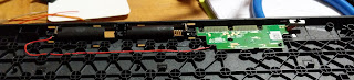
Strip the other end of the wire you just soldered onto the switch. This wire will run from the switch to the +ve terminal on the board. Solder it to the board +ve terminal by placing the wire on top of the existing solder pad and heating the wire until the solder flows over the wire. If you have issues with the wire popping out once you remove the iron, before the solder cools, you can press it down with some tweezers or you can place helping hands or something close enough that it won't pop free.

Note that in the above image the black -ve wire is present, just bent behind the circuit board.
If you have a multimeter, put one probe or clip on the +ve terminal of the battery compartment and the other on the +ve terminal of the circuit board. Use the conductivity test mode (sometimes labeled diode test, or just a beep/speaker icon) to verify that when the switch is closed the circuit is closed and current will flow (you get a beep). Check that when the switch is opened the circuit is broken and current does not flow (no beep). Yay? Yay!
Place the circuit board back in its original location. Route the extended wire wherever you can, as space is tight. There are notches where the original wire ran, use them as much as possible. Keep the wire away from the locations the keys will go once the keyboard is reassembled. I didn't have to cut any new notches or anything, though that's an option too.

Screw the circuit board in. Orient the switch where you want it.
Cut a suitable opening in the casing for the switch's lever or slide. Try to keep it small, you don't want the whole switch coming out. I used a rotary multitool for this, then refined the hole with some jewelers' files. But you can use whatever you want, a household powerdrill with a 2mm bit might well do, or a carefully used router, whatever. Cut smaller than needed, fit-check, and widen until it fits nicely but without excess wiggle.
Reassemble the keyboard.

Hopefully it works!
If it works, you may wish to open up the case to expose the switch and glue the switch to the keyboard base using a strong epoxy glue or similar. Be careful not to glue the moving parts of the switch! I didn't bother, it's held in place well enough by being wedged in place between the keyboard front and back.
There you go. No more flat batteries.
Wouldn't it be nice if they'd just included a switch in this otherwise excellent keyboard to start with?
Handy tools
You don't need any of these. But I used all of them in this job, so I figured I'd list what I find to be useful.
A decent quality temperature controlled electric soldering iron or soldering station. You don't need one, they just make things easier.
A set of helping hands or similar. In a pinch you can use something like a nylon jaw desk clamp (gently), ask a friend, or pretend to be an octopus.
Wire strippers. They make getting insulation off cleanly so much easier. If you don't have any, don't fret. You can carefully cut most of the way into the insulation using edge cutters, the cutting edge of regular household pliers, or even scissors, then pull the insulation off. If you break the wire you just cut it below the break and try again.
Heatshrink tubing. This stuff is magic. Slip it over a wire or other exposed junction, heat it up with a heat gun or small blowtorch (from a distance) or lighter or whatever suits you and it shrinks on to mould to and grip the joint, giving it both physical reinforcement and electrical isolation. Wonderful stuff, available at any electronics hobby store. If you don't have any you can use electrical tape from any hardware store, or you could use it as an excuse to play with silicone self-fusing tape because that stuff is awesome.
A small butane jet torch, a heat gun, or similar. Be careful with jet torches though, it's hard to control the heat application and you can go from "not doing anything" to "incinerated" rather rapidly.
A digital multimeter with a connectivity-test mode. Touch the leads to things and it beeps if there's a very low resistance path i.e. they're electrically connected, as well as many many other useful jobs.
Soldering fingers / wire joiner jig / wire soldering jig. If you have access to a 3D printer this one on Thingiverse is good. Helping hands work fine, I just find a joining jig to be more stable and less likely to pinch the insulation.
Heatsink clips/tweezers, which help make it easier to solder things without melting insulation or frying components. Some bathroom tweezers with an elastic band wound tightly around them work in a pinch.
Needle nose pliers and/or fine round-nose pliers to make handling small wires and components easier
A multipurpose rotary cutting tool (like a Dremel multitool or similar). Great for fiddling with casings etc.
Mini files or jewellers files. For when you need to remove small amounts of material these are just great.
A pin vise (basically a chuck on a grip handle) and set of micro drill bits. For when power drills aren't precise enough.
A really small, low power power drill. Oddly enough the cheapest and nastiest cordless power drills seem to work well for this. Not much need if you have a rotary multitool and a variable chuck for it.
No comments:
Post a Comment
Captchas suck. Bots suck more. Sorry.